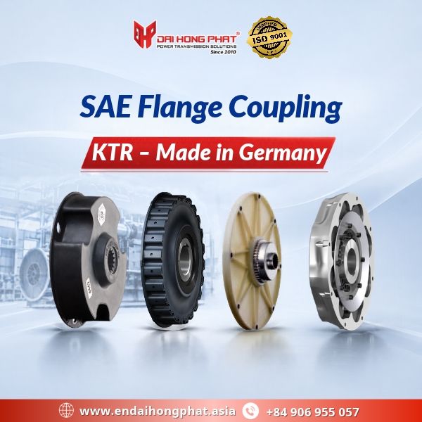
An SAE Flange Coupling is a power transmission solution commonly used in diesel engines, construction machinery, generator sets, and hydraulic equipment. KTR Systems, a German manufacturer specializing in power transmission technology, offers various coupling series with different technical characteristics to meet requirements for torque transmission, torsional vibration damping, and engine flywheel connections.
Selecting the right SAE Flange Coupling helps engineers ensure adequate torque capacity, reduce vibration, and maintain compatibility between components in the drive system.
1. What Is an SAE Flange Coupling?
An SAE Flange Coupling is a mechanical coupling designed with a flange connection that interfaces with an engine flywheel according to the applicable SAE dimensional standard.
Depending on its design, the coupling may incorporate flexible elastomeric elements or a curved-tooth gear mechanism to transmit torque between the engine and the driven equipment.
In industrial power transmission systems, SAE standards facilitate the identification of compatible connection dimensions. However, engineers must still verify installation drawings, shaft diameters, and the torque capacity of each coupling model.
2. KTR SAE Flange Coupling Series – Germany
KTR develops a wide range of SAE Flange Coupling solutions to meet different industrial power transmission requirements.
KTR SINULASTIC® – Torsional Vibration Damping
+ The SINULASTIC® series incorporates flexible elastomeric elements to reduce torsional vibrations and minimize the effects of fluctuating loads on the drive system.
+ SINULASTIC® A, B, and T versions feature different connection configurations and installation characteristics, allowing engineers to select a suitable design for specific applications.
See more product specifications: KTR Flange couplings SINULASTIC®
KTR MONOLASTIC® – Compact Flexible Design
+ MONOLASTIC® is a KTR shaft coupling series featuring an integrated elastomeric design that accommodates shaft misalignment within specified limits.
+ MONOLASTIC® SAE and MONOLASTIC® Type with 3 Holes have different connection arrangements. Engineers should distinguish between SAE flywheel flange connections and three-hole mounting configurations when selecting a coupling.
See more product specifications: KTR Flange couplings MONOLASTIC®
KTR VAROLASTIC® – Progressive Torsional Stiffness
+ VAROLASTIC® F and FD incorporate EPDM elastomer rollers and feature progressive torsional stiffness, meaning that torsional stiffness increases with transmitted load.
+ This SAE Flange Coupling series is suitable for drive systems requiring torsional vibration control under variable operating loads.
+ The VAROLASTIC® FD version also features an integrated mechanical stop designed to limit relative movement in the event of elastomer element failure.
See more product specifications: KTR Flange couplings VAROLASTIC®
KTR BoWex® – Curved-Tooth Gear Coupling Technology
+ BoWex® couplings use a curved-tooth gear mechanism for torque transmission and are available in various configurations for diesel engine flywheel connections.
+ BoWex FLE-PA, FLE-PAC, and BoWex-ELASTIC HE differ in their construction, torque ratings, and torsional flexibility.
See more product specifications: KTR Flange couplings BoWex®
These SAE Flange Coupling solutions are worth considering for applications involving diesel engines, hydraulic pumps, and industrial power transmission equipment.
3. International DNV and Bureau Veritas Certifications for KTR BoWex
Several KTR BoWex coupling types have received type approval from internationally recognized marine classification societies.
+ DNV: Type Approval Certificate No. TAM00000J1, valid until April 11, 2028, covers BoWex FLE-PA, FLE-PAC, and other specified coupling types listed in the certificate.
+ Bureau Veritas (BV): Type Approval Certificate No. 02966/I0 BV, valid until May 14, 2030, covers BoWex-ELASTIC HE, FLE-PA, FLE-PAC, and additional BoWex coupling types within the approved scope.
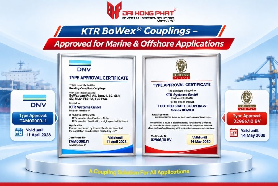
These certifications confirm that the approved coupling types comply with the applicable marine classification requirements, subject to the operating conditions and technical limitations specified in each certificate.
For projects requiring marine classification approval, engineers must verify the exact coupling model, size, and operating conditions.
It is important to note that not every SAE Flange Coupling is automatically covered by these certifications.
4. How to Select the Right SAE Flange Coupling
Selecting a suitable SAE Flange Coupling requires careful evaluation of engine specifications, driven equipment characteristics, and actual operating conditions.
Choosing a coupling based solely on engine power or shaft diameter may result in incorrect sizing, excessive vibration, or premature component failure.
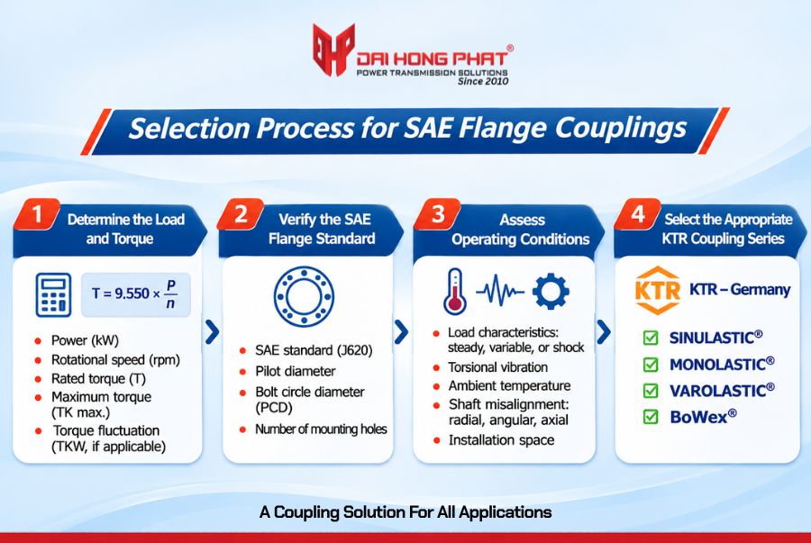
4.1. Determine Engine Power and Transmission Torque
The first step is to collect the engine power (kW), rotational speed (rpm), and load characteristics of the driven equipment.
The nominal transmission torque can be calculated using the following formula: T = 9,550 × P / n (Nm)
Where:
+ P: Transmitted power (kW).
+ n: Rotational speed (rpm).
+ T: Nominal transmission torque (Nm).
Example:
A diesel engine rated at 150 kW and operating at 1,500 rpm produces a nominal torque of approximately 955 Nm.
When selecting a KTR shaft coupling, engineers must verify the rated coupling torque (TKN), maximum permissible torque (TK max.), and the appropriate service factor.
For systems subject to significant torsional vibrations, the permissible alternating torque amplitude (TKW) should also be evaluated according to the manufacturer’s technical documentation.
4.2. Verify SAE Flange Standards and Mounting Dimensions
Engineers must verify the engine flywheel dimensions according to SAE J620, including:
+ Pilot or centering diameter.
+ Bolt circle diameter (PCD).
+ Number and arrangement of mounting holes.
Additional checks should include shaft diameter, keyway configuration, hub length, and available installation space.
Technical note: An SAE engine flywheel flange and an SAE hydraulic pump mounting flange are different mechanical interfaces. They should not be considered interchangeable without checking the relevant installation drawings and dimensional specifications.
4.3. Evaluate Actual Operating Conditions
For construction machinery, generator sets, and hydraulic power systems, the following operating factors must be considered:
+ Variable and shock loads: Verify the coupling’s maximum torque capacity during startup, sudden load changes, and transient operating conditions.
+ Torsional vibration: Evaluate the coupling’s torsional flexibility, stiffness characteristics, and vibration damping capability.
+ Operating temperature: Check the permissible temperature range of the elastomeric elements.
+ Shaft misalignment: Verify the permissible angular, radial, and axial misalignment limits for the selected coupling model.
These factors are particularly important in heavy-duty industrial applications where load fluctuations and continuous operation may affect coupling performance.
4.4. Select the Appropriate KTR Coupling Series
Depending on the drive system requirements, engineers may consider SINULASTIC®, MONOLASTIC®, VAROLASTIC®, or BoWex®.
Flexible coupling series are suitable for applications requiring torsional vibration control, while BoWex FLE-PA and FLE-PAC use curved-tooth gear technology with different torque transmission characteristics.
Technical recommendation: Before placing an order, confirm the exact coupling model, size, SAE flange configuration, shaft diameter, and installation drawings
For equipment requiring DNV or Bureau Veritas approval, the applicable certification scope must also be verified for the selected coupling type.
DAI HONG PHAT supplies SAE Flange Coupling products from KTR Systems, Germany, and supports customers in selecting suitable coupling solutions based on technical requirements and actual operating conditions.
Correct selection of the coupling model, dimensions, and mounting configuration is essential for reliable power transmission, stable operation, and efficient maintenance.
Contact DAI HONG PHAT for technical consultation and genuine KTR shaft coupling solutions.
—————-/—————–/—————–/—————–/—————–
– Hotline: +84906.955.057 | – Email: info@dhp-corp.com.vn
– Website: https://en.daihongphat.asia/ – https://khopnoitruc.com/ – https://ringfeder.com.vn/
- How To Identify Genuine NKE Bearings You Should Know?
- Characteristics and Applications of Locking Assembly Ringfeder RfN 7515
- What is Flexible Shaft Coupling? Types of Flexible Shaft Couplings in 2025
- Understanding the MMC: Combined Cooler (Mobile Machinery Cooler) by KTR Systems
- Features and Characteristics of the Locking Assembly Ringfeder RfN 7013.1