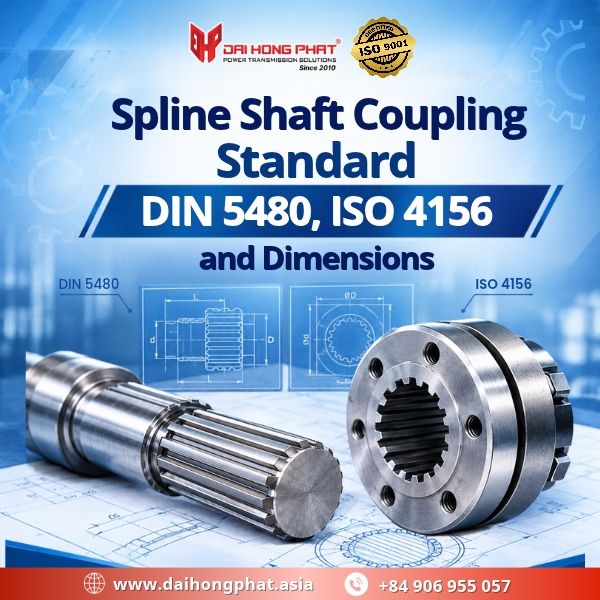
Splines are widely used for torque transmission in industrial drive systems, particularly in applications requiring a secure connection between a shaft and a hub. To ensure proper assembly and reliable power transmission, selecting the correct Spline Shaft Coupling Standard is essential.
Standards such as DIN 5480 and ISO 4156 specify important requirements for spline profiles, dimensions, and tolerances. This article explains spline configurations, how to interpret technical specifications, and key considerations when selecting couplings with spline connections.
1. What Is a Spline Shaft Coupling Standard?
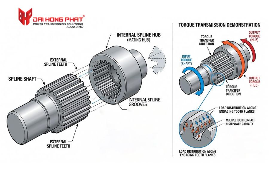
A spline is a mechanical connection consisting of multiple teeth and grooves evenly distributed around the circumference of a shaft. The internal bore of the hub or coupling has a corresponding profile that engages with the external teeth of the shaft.
This configuration transmits torque between two mechanical components and, depending on the design, may also allow axial movement.
Functions of splines in power transmission shaft couplings:
+ Transmit torque between the shaft and hub.
+ Distribute loads across multiple contacting teeth.
+ Improve centering and connection stability when properly designed.
+ Allow axial movement in sliding spline configurations.
Common spline profiles:
+ Straight Spline: Features straight tooth flanks and a relatively simple geometry.
+ Involute Spline: Uses an involute tooth profile and is commonly applied in drive systems requiring reliable torque transmission and dimensional accuracy.
+ Triangular Spline: Features triangular-shaped teeth and is used in certain specialized mechanical applications.
Selecting the appropriate Spline Shaft Coupling Standard requires consideration of the actual spline profile, shaft dimensions, torque requirements, and compatibility between the external shaft spline and internal hub spline.
|
FOR ANY QUESTIONS OR QUOTATION REQUESTS, PLEASE CONTACT: |
2. Common Spline Standards: DIN 5480 and ISO 4156
2.1 DIN 5480 – Involute Splines Based on Reference Diameters
DIN 5480 is a German standard developed to specify involute spline connections between shafts and hubs. Its distinguishing feature is the use of a reference diameter as the basis for defining spline dimensions, rather than relying entirely on the module series used in ISO 4156.
The standard specifies a nominal pressure angle of 30°, primarily uses flank centering, and establishes a tolerance system to control spline fit and interchangeability.
When referring to DIN 5480, it is important to understand the purpose of its individual parts:
+ DIN 5480-1: General principles and design fundamentals.
+ DIN 5480-2: Nominal dimensions and inspection dimensions.
+ DIN 5480-15: Inspection of spline connections.
+ DIN 5480-16: Requirements relating to spline manufacturing tools. The current publication status should be checked before using it as a formal standard reference.
2.2 ISO 4156 – Metric Module Involute Splines
ISO 4156 specifies straight cylindrical involute splines with parallel axes and side-fit connections. This standard uses the metric module system and is divided into three parts:
+ ISO 4156-1: Generalities and design parameters.
+ ISO 4156-2: Geometrical dimensions and inspection dimensions.
+ ISO 4156-3: Inspection requirements and methods.
ISO 4156 specifies three nominal pressure angles: 30°, 37.5°, and 45°. The selected pressure angle and module must comply with the dimensional series defined in the applicable standard.
2.3 Comparison of DIN 5480 and ISO 4156
| Criteria | DIN 5480 | ISO 4156 |
|---|---|---|
| Tooth profile | Involute | Involute |
| Dimensional basis | Reference diameter | Metric module system |
| Pressure angle | 30° | 30°, 37.5°, 45° |
| Centering method | Primarily flank centering | Flank centering |
| Applications | Detachable, sliding, or fixed shaft-to-hub connections | Detachable, sliding, or fixed shaft-to-hub connections |
| Document structure | Separate parts covering principles, dimensions, inspection, and tooling | Three parts covering principles, dimensions, and inspection |
Technical note: These two standards use different dimensional systems. Compatibility cannot be determined solely by comparing the outside diameter, number of teeth, or pressure angle. The complete tooth geometry, tolerances, and centering method must be checked before confirming interchangeability.
|
FOR ANY QUESTIONS OR QUOTATION REQUESTS, PLEASE CONTACT: |
3. Spline Dimensions and How to Interpret Technical Specifications
When referring to a Spline Shaft Coupling Standard, the basic geometrical parameters must be identified to ensure accurate fitting between the external shaft spline and the internal spline bore.
Key spline parameters:
| Symbol | Description |
|---|---|
| m | Spline module |
| z | Number of spline teeth |
| α | Pressure angle |
| d | Reference or pitch diameter, as defined by the applicable standard |
| da | Major diameter or tooth-tip diameter |
| df | Minor diameter or tooth-root diameter |
| L | Engagement length |
The symbols and methods used to define individual dimensions may vary depending on the standard. Therefore, the relevant dimensional tables and technical documentation must be used. DIN 5480 dimensions should not be directly applied to ISO 4156.
3.1 Understanding DIN 5480 Designations
A DIN 5480 designation may contain several identification elements, such as:
+ N: Internal spline or hub designation.
+ W: External spline or shaft designation.
+ Subsequent parameters identify the reference diameter, module, number of teeth, and tolerance class according to the applicable standard.
This is a general explanation of the designation structure. For ordering or manufacturing, the complete designation must be verified against the applicable DIN 5480 edition and the engineering drawing. An illustrative example should never replace an approved manufacturing specification.
3.2 Spline Tolerances and Fits
Tolerances directly affect assembly, torque transmission, and the service life of a spline connection. Common fit conditions include:
+ Clearance Fit: Allows convenient assembly and disassembly and may be suitable for applications requiring axial movement.
+ Transition Fit: Provides a balance between positioning accuracy and assembly convenience, depending on the design.
+ Interference Fit: Provides a tighter connection for applications specifically designed to accommodate this type of fit.
The centering method between the shaft and internal spline must also be identified. Depending on the configuration and standard requirements, centering may be based on the tooth flanks or specified diameters.
When designing or inspecting a spline connection, the following parameter groups should be considered:
| Parameter Group | Items to Be Identified |
|---|---|
| Geometry | Number of teeth, module or reference diameter, pressure angle |
| Dimensions | Major diameter, minor diameter, tooth dimensions, and engagement length |
| Tolerances | Dimensional deviations, profile deviations, and tolerance classes |
| Fit | Clearance, interference, and centering method |
| Inspection | Inspection dimensions, gauges, and appropriate measurement methods |
For DIN 5480, DIN 5480-1 and DIN 5480-2 should be consulted to determine the design principles, nominal dimensions, and inspection dimensions. DIN 5480-15 should be referenced for inspection and acceptance.
For ISO 4156, all three parts should be considered: ISO 4156-1, ISO 4156-2, and ISO 4156-3. Dimensional information in Part 2 should not be used in isolation without considering the tolerance and inspection requirements in Parts 1 and 3.
4. Inspection Procedure for Identifying Spline Shaft Dimensions
To select the correct Spline Shaft Coupling Standard, actual shaft parameters must be inspected rather than relying only on the shaft outside diameter.
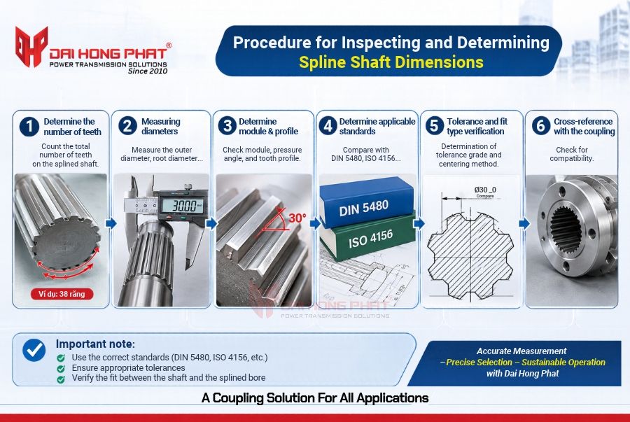
The inspection process can be carried out in six steps:
+ Step 1: Identify the Number of Teeth. Count the teeth accurately around the circumference of the spline shaft. This is a basic parameter for comparison with engineering drawings or standard dimensional tables.
+ Step 2: Measure the Diameters. Use suitable measuring instruments to check the major diameter, minor diameter, and other relevant dimensions. Measurements taken with a standard caliper should be considered preliminary only.
+ Step 3: Identify the Module and Tooth Profile. Check the tooth geometry, module, and pressure angle. For involute splines, specialized measurement methods or equipment may be required to accurately determine the tooth profile.
+ Step 4: Identify the Applicable Standard. Compare the measured parameters with engineering drawings, manufacturer documentation, or relevant DIN 5480, ISO 4156, and other applicable standard references.
+ Step 5: Check Tolerances and Fit Conditions. Determine the tolerance class, centering method, and compatibility between the external shaft spline and internal spline bore.
+ Step 6: Verify Compatibility with the Coupling. Check the compatibility between the spline shaft and coupling hub. Also consider torque requirements, rotational speed, and actual operating conditions.
Technical note: For precision manufacturing or acceptance inspection, suitable inspection gauges, specialized measuring equipment, or appropriate profile measurement methods should be used. Tolerance classes should not be determined solely from a few caliper measurements.
5. Applications and How to Select the Right Spline Coupling
Spline connections are used in a wide range of industrial drive systems where torque must be transmitted between mechanical components.
Common applications include:
+ Motor and gearbox drive systems.
+ Industrial machinery and manufacturing equipment.
+ Transmission systems in the steel, cement, and mining industries.
+ Lifting equipment and construction machinery.
+ Drive assemblies requiring detachable shaft connections or axial movement.
Key factors to consider when selecting a spline coupling:
1. Standard and Tooth Profile: Identify the correct DIN, ISO, or other applicable standard specified in the engineering drawing.
2. Shaft Dimensions: Check the number of teeth, module, diameters, and engagement length.
3. Fit Tolerances: Ensure compatibility between the external shaft spline and internal spline bore.
4. Operating Requirements: Consider torque, rotational speed, load conditions, and duty cycle.
5. Operating Environment: Evaluate temperature, vibration, working environment, and maintenance requirements.
Selecting the correct Spline Shaft Coupling Standard helps ensure proper assembly and contributes to the stability and service life of the entire transmission system.
Dai Hong Phat – A Coupling Solution For All Applications.
References
+ DIN 5480-1:2026-05 – Involute splines based on reference diameters – Part 1: Generalities.
+ DIN 5480-2:2025-10 – Involute splines based on reference diameters – Part 2: Nominal and inspection dimensions.
+ DIN 5480-15:2025-10 – Involute splines based on reference diameters – Part 15: Inspection.+
+ ISO 4156-1:2021 – Straight cylindrical involute splines – Metric module, side fit – Part 1: Generalities.
+ ISO 4156-2:2021 – Straight cylindrical involute splines – Metric module, side fit – Part 2: Dimensions.
+ ISO 4156-3:2021 – Straight cylindrical involute splines – Metric module, side fit – Part 3: Inspection.
—————-/—————–/—————–/—————–/—————–
– Hotline: +84906.955.057 | – Email: info@dhp-corp.com.vn
– Website: https://en.daihongphat.asia/ – https://khopnoitruc.com/ – https://ringfeder.com.vn/
- Applications of The Rotex GS Coupling in Industrial
- Comparison of 5 Common Types of Shaft Couplings in Mechanical Industry
- WHAT IS A COOLING TOWER AND HOW DOES IT WORK?
- BREAKING NEWS: RATHI TRANSPOWER INDIA OFFICIALLY MERGES INTO RINGFEDER GERMANY
- Dai Hong Phat – An Authorized Distributor for NKE Bearings in Vietnam